The basic deviation is used to determine the position of the tolerance zone relative to the zero line. Different tolerance zone positions and reference parts form different fits. The number of basic deviations determines the number of coordination types. The national standard specifies 28 basic deviations for holes and shafts, each represented by Latin letters. The holes are represented by uppercase letters, and the shafts of gantry imaging measuring instruments are represented by lowercase letters. They form a basic deviation sequence.
One. In the basic deviation of the axis, the basic deviation of a~g is the upper deviation, while in the basic deviation of the hole, the basic deviation of a~g is the lower deviation, and the absolute value decreases sequentially;
2. The basic deviation between axis h and hole h is zero;
III. The basic deviation between axis JS and hole JS is symmetrical relative to the zero line;
In general, a~h forms a clearance fit with the reference hole, where a, B, and C are used for large clearance fits, and D, e, and F are mainly used for rotational motion under general lubrication conditions. J~N forms a transitional fit with the reference hole, while P~ZC forms an interference fit with the reference hole.
The basic deviation sequence diagram only displays one end of the tolerance zone, so the code of any tolerance zone is represented by a combination of the basic deviation code and the tolerance grade number.
Understanding the basic deviation relationship of the hole axis can deeply consider the determination method of fitting accuracy in design. Determine the dimensional tolerance of the hole axis based on the relationship between fit tolerances.
The laser option of the image
Measuring Instrument can provide high-precision single point focusing and surface scanning functions, low energy visible light diode laser, emitting light sources to the surface of parts, and receiving reflection light sources to obtain data. The manual image measuring instrument obtains high-resolution surface contours by scanning the surface of parts with a laser.
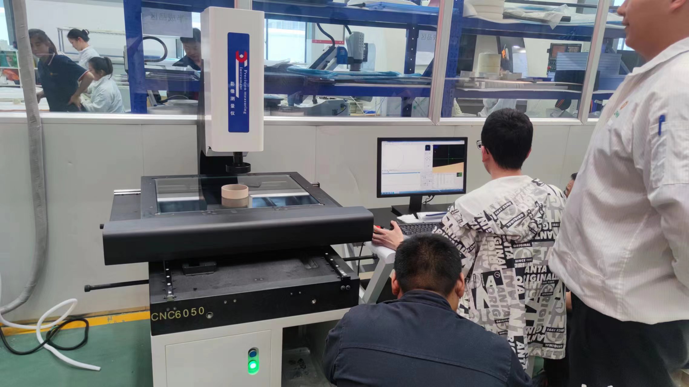
The optional laser sensors for image measurement instruments include QVTTL (coaxial laser lens) or off axis DRS laser. Different models have been configured on different models, which are suitable for different part surfaces, such as diffuse reflection or mirror surface, as well as the inclination of the part surface. Although the QVI off axis DRS laser used for image measurement instruments deviates from the lens center of the instrument, it can be coaxial and applicable after calibration, and can be controlled by a program. The gantry image measuring instrument is easy to use
The single point trigger probe makes OGP intelligent oscilloscope image measurement instruments more diverse. The 2.5-dimensional measuring instrument contact probe can be used to measure features or surface boundaries that cannot be touched by the image.
The probe measurement can be a step in the measurement process of a horizontal tensile testing machine measurement-x or measuremin3D image measuring instrument. The QVI tensile testing machine's image coaxial calibration unique probe ensures that all sensors are in the reference coordinate system and can be flexibly measured with any sensor.
The measurement accuracy of the series probe can be ensured through the calibration of the reference ball and software. The probe, detachable module, probe bracket, and probe can be purchased from QVI or provided by the customer themselves. Trigger detectors can be configured in smartscope vantagetm, smartscope flashtm, smartscope ziptm, and smartscope atstm systems. All probes can be collected, stored, and scaled under software control. Configure the working principle and mode of the probe according to the QVI image measuring instrument


